JavaScript is disabled
Our website requires JavaScript to function properly. For a better experience, please enable JavaScript in your browser settings before proceeding.
Messages
1,268
Reactions
1,447
Portable air conditioner…. Was junk but is holding refrigerant so I thought I'd try and fix.

First eBay order I got the wrong board…. ($30) I don't know how to refine search results enough for these units. Maybe I'll try mod. and ser. again.

Then I thought I can just use the part I need.

I'm not really set up for fine circuit repair…. But I feel okay enough to replace start components. Both relays are the same across VA

Haaaa…. Was gonna just try and wire a hard start kit in here but figured it's too dumb…..the 3-1 that is, for these fancy units.

Question….
Looks like a resistor across coil on relay. Likely fried too…?
Or what is that?

(Side question)
….. anyone got time to replace this for me? Hoping someone has a bench set up already for this work. Some strange people in this place. I can ship and pay.

But if I can pull relay and verify resistor is good……. All I'd need are words of encouragement.

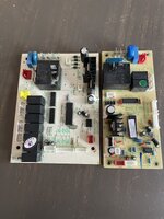
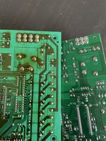
IMG_3814.jpeg IMG_3815.jpeg
 
I've seen circuits where a diode is placed across relays coils, to prevent getting a negative voltage spike on the line from the coil and damaging other components. For example, you have +12V on the coil to energize the relay. When you remove the 12V, the coil tries to maintain current by inducing -12V. The diode clamps that voltage to near zero. You would have to separate one end of the diode from the relay coil to verify that the diode was short in one direction and open in the other.

OTOH, it's been a long time since I looked at these, so what do I know, anyway? 🙁
Kind of looks like a diode, doesn't it? Hard to be sure from the picture.

@NobullSKS, can we get a closer look at the resistor? Basically, if the red part looks more like a tiny coil of wire in a clear cover, it's probably a diode and may be OK. If it looks more like a resistor that got some of the cover fried off by heat, that's probably what it is.
 
@Flopsweat

Y'all are likely on to it. But it looks painted like it has a resistance rating. I believe I see black and white under clear coat


Guess I could pull it… compare to relay coil OHM and find out if it's a resistor.

Would I use DC to check diodes?

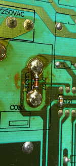
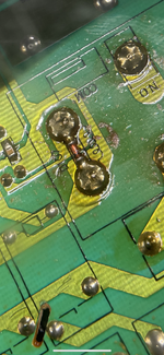
IMG_3821.png IMG_3818.png
 
Last Edited:
@Flopsweat

Y'all are likely on to it. But it looks painted like it has a resistance rating. I believe I see black and white under clear coat


Guess I could pull it… compare to relay coil OHM and find out if it's a resistor.

Would I use DC to check diodes?

View attachment 1423249 View attachment 1423250
That's a diode. Here's how you determine value and polarity:


As Bacchus mentioned, you want to lift one end of the diode to disconnect it from the circuit. Then you can use your multimeter to test it:


I'm not sure how delicate it is going to be in terms of heat. The ones I dealt with were manufactured a few decades ago, and were mostly slightly larger than that one. I never had issues with soldering or desoldering them. Looking at the board, I think a standard soldering iron and some wick would be OK. Anybody with more recent experience, please feel free to correct me.
 
That's a zener diode, BTW.
It's pretty darn small, but it should have some numbers printed on it for it's voltage.

This zener is doing double duty, in normal operation it's limiting the voltage, likely the zener value is very close to the relay coil operating voltage.
When power to the relay is cut, it then acts to clamp any back feed voltage produced by the relay coil.

It's not common to use a zener diode like this, we usually use a silicon diode in the 1N400x family instead.
 
Would I use DC to check diodes?

Flopsweat's link probably will show you the process.

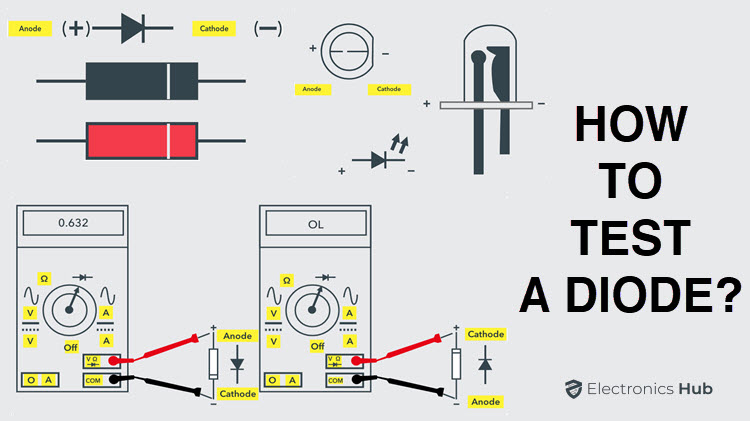
But if not, if you test the diode with a DMM, remove power to the circuit. The DMM dial will probably have a diode icon at one of the switch positions. You'll have to remove one end of the diode from the circuit and put the probes across it: one probe on each end of the diode, observing polarity. The DMM will source current and measure voltage drop.
 
Last Edited:
The component in your picture shows "D107" for the reference designator; the 'D' is for diode. The black band you see is the indicator for the cathode end of the diode.

It's definitely a diode!

Some diodes will have 'CR' for the reference designator, for "crystal rectifier."
 
That's a zener diode, BTW.
It's pretty darn small, but it should have some numbers printed on it for it's voltage.

This zener is doing double duty, in normal operation it's limiting the voltage, likely the zener value is very close to the relay coil operating voltage.
When power to the relay is cut, it then acts to clamp any back feed voltage produced by the relay coil.

It's not common to use a zener diode like this, we usually use a silicon diode in the 1N400x family instead.
This guy. ☝️ Listen to this guy. He's more "current" than I. :)

Flopsweat's link probably will show you the process.

But if not, if you test the diode with a DMM, remove power to the circuit. The DMM dial will probably have a diode icon at one of the switch positions. You'll have to remove one end of the diode from the circuit and put the probes across it: one probe on each end of the diode, observing polarity. The DMM will source current and measure voltage drop.
This guy too. ☝️
 
Wonderfully everyone. Thank you
Always like new different projects.
Think I'm going have at it.

If it's still dead… double check to grounds….
If it's still dead…. Gonna recover gas and let loose the kids with tools.
Thx again
 
One more thing. In your very first photo, it shows a larger and smaller circuit board side by side. Both boards have a very large square black component, marked HONGFA. I'm guessing from their markings that they are transformers.

The one on the larger (left) circuit board looks like it has some major damage, like it melted through. Is that real, or just the photo?
I didn't even notice that on my smartphone.

That's a power relay, and it's definitely toasted. A common issue on other appliances like dryers....
 
When I zoom in I can see the COM (common), NC (normally closed), and NO (normally open) markings next to the posts, so you're right, it is a relay.

Lots of relays on this board, there's also a stack of seven smaller relays on the lower left of the bigger board. Tick ... tick ... tick ...

I would definitely start by replacing the melted relay. And that's No Bull ! ;)
 

Upcoming Events

Oregon Arms Collectors April 2024 Gun Show
Portland, OR
Centralia Gun Show
Centralia, WA
Albany Gun Show
Albany, OR
Falcon Gun Show - Classic Gun & Knife Show
Stanwood, WA
Wes Knodel Gun & Knife Show - Albany
Albany, OR

New Resource Reviews

New Classified Ads

Back Top